TM 5-3805-262-20
REMOVAL (SHEET 2 OF 3)
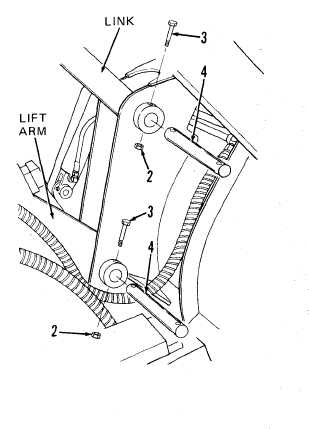
(2) At top of loader bucket assembly where link is secured to loader bucket
assembly, remove lock nut (2) and capscrew (3).
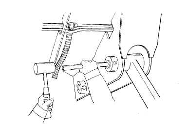
( 3 ) P r e s s p i v o t p i n ( 4 ) f r o m b u c k et
using 1-7/8 inches diameter rod
and hammer as shown.
( 4 ) R e p e a t s t e p s ( 2 ) a n d ( 3 ) a b o v e to
remove lock nut (2), capscrew (3),
and pivot pin (4) securing lift arm
to loader bucket assembly.
(5) Repeat steps (1) through (4) to disconnect link and lift arm from remain-
ing side of loader bucket assembly.
I n f o l l o w i n g s t e p , d o n ’ t a l l o w l i n k s t o s t r i k e p o l i s h e d s u r f a c e o f t i l t
c y l i n d e r a s s e m b l i e s r o d .
T o d o s o m a y c a u s e d a m a g e t o c y l i n d e r
assemblies resulting in hydraulic oil leakage and requiring replacement
and repair of cylinder assemblies .
(6) Swing links up and over bellcrank assemblies and secure in position so
that they cannot move. Make sure that links don't strike and damage po-
l i s h e d s u r f a c e o f t i l t c y l i n d e r a s s e m b l i e s r o d.
12-21