TM 5-3805-262-20
3-28. STE/lCE DESCRIPTION AND OPERATION (CONT)
d. Transducer Kit (TK).
The TK contains a pulse tachometer transducer, a 0-1000
psig pressure transducer, -30 in. Hg to 25 psig pressure transducer, necessary adap-
ters (bushings, tees, adapters, connectors, plugs, and nipples) for connecting pres-
sure transducers to equipment under test, and a current probe. Refer to TM 9-4910-
571-12&P for a detailed description and listing of TK components.
e. Cable Assemblies.
There are six cable assemblies included. Two of these ca-
bles (W1 and W3) are not used during loader troubleshooting. Four cables may be used,
in troubleshooting the loader. If necessary, two transducer cables (W4) can be
joined using an adapter supplied with the TK to make one long cable. The other two
cables used during loader troubleshooting are test probe cable W2 used for voltage
measurements and power cable W5. Refer to TM 9-4910-571-12&P for a detailed descrip-
tion and listing of cable assemblies.
3-29. STE/ICE SET-UP PROCEDURES
Refer to TM 9-4910-571-12&P for STE/ICE power up procedures and confidence test pro-
cedures, Set-up procedures to interface STE/ICE with the loader are covered in de-
tail in the following troubleshooting procedures.
3-30. ENGINE TROUBLESHOOTING
MALFUNCTION
TEST OR INSPECTION
CORRECTIVE ACTION
1. ENGINE WILL NOT CRANK.
Step 1.
Open radiator grille at rear of loader .
Connect STE/ICE power cable W5 connector P1 to J1 of VTM.
Check that VTM PUSH ON/PULL OFF switch is in OFF position.
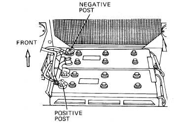
Connect power cable W5 red clip lead to loader battery positive post
and black clip lead to loader battery negative post.
3-201