TM 5-3805-262-20
3-33. STARTING SYSTEM TROUBLESHOOTING (CONT)
MALFUNCTION
TEST OR INSPECTION
CORRECTIVE ACTION
1. STARTER DOES NOT CRANK (STARTER SOLENOID DOES NOT CLICK) (Cont).
Step 4.
Step 5.
Step 6.
(Cont).
Move red test clip of test probe cable W2 to bottom terminal of
loader 30 ampere circuit breaker .
Press and release TEST button.
VTM should display 24 volts.
a. If VTM displays 24 volts for both terminals, check wiring con-
nection between loader 30 ampere circuit breaker and ignition
key switch connector BATT terminal.
Repair or replace wiring or
connector as necessary (page 5-168 or 5-174).
If wiring and connector are okay, remove right instrument panel
(page 5-48) and replace ignition key switch (page 5-53).
b. If VTM displays 24 volts at one terminal and zero at remaining
terminal, replace loader 30 ampere circuit breaker (page 5-26) .
c. If VTM displays zero for both terminals, go to step 5 below.
Move red test clip of test probe cable W2 to large left terminal of
s t a r t e r r e l a y .
Press and release TEST button.
VTM should display 24 volts.
a. If VTM displays 24 volts,
check wires between starter relay ter-
minal and 30 ampere circuit breakers. Replace wires as necessary
(page 5-26).
b. If VTM displays zero, check cable between starter solenoid BAT
terminal and starter relay terminal. Replace cable as necessary
(page 5-16).
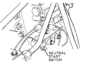
Move red test clip of test probe
cable W2 to neutral start switch
terminal to which white wire is
connected.
Press and release TEST b
Crank engine and watch VTM
d i s p l a y.
VTM should display 24 volts.
Turn ignition key switch to off
p o s i t i o n.
u t t o n.
3-268