TM 5-3805-262-34
4-4. FRONT AND REAR AXLES DIFFERENTIAL ASSEMBLY MAlNTENANCE (CONT)
a. Differential Carrier (Cont).
Disassembly (SHEET 2 OF 4)
(5)
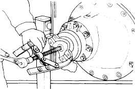
Remove two cotter pins (1) using pliers.
(6)
Remove four capscrews (2), washers (3), and two differential caps (4).
(7)
If necessary for replacement, remove four dowel pins (21) from differen-
tial caps (4).
(8)
Remove two adjusting rings (5) from differential case and gear assembly.
When using chain hoist to remove or install parts, be sure chain hoist
is securely fastened to the part and that all slack in chain is taken
up. Failure to do so could cause serious injury due to the part falling
on you.
If you are injured by falling equipment, obtain medical aid
immediately.
(9)
(10)
(11)
(12)
(13)
(14)
(15)
(16)
(17)
(18)
(19)
(20)
4-220
Insert steel bar through differential case and gear assembly. Connect
chain hoist to steel bar and remove differential case and gear assembly
from differential carrier (27).
Remove two bearing cups (6) from differential case and gear assembly.
Position flange holding tool on yoke (9) and secure using two 7/16-20NF
by one inch long capscrews. Then, remove nut (7) and washer (8).
Remove two 7/16-20NF capscrews and
flange holding tool. Then, using
puller, remove yoke (9).
Remove deflector (10) from cage (18).
If necessary, use puller.
Remove eight capscrews (11) and
washers (12) from cage (18).
Using soft hammer, strike pinion (23)
shaft end at differential cap (4)
side of differential carrier (27).
Remove pinion (23) and cage (18) from differential carrier (27).
Remove shims (13). Wire shims together
bly.
Put pinion (23) and cage (18) assembly
mounting surface facing downward.
to prevent loss and aid reassem-
in hydraulic press, cage (18)
Press pinion (23) shaft from cage (18).
Put cage (18) in hydraulic press with mounting surface facing upward.