TM 5-3805-262-34
DISASSEMBLY (SHEET
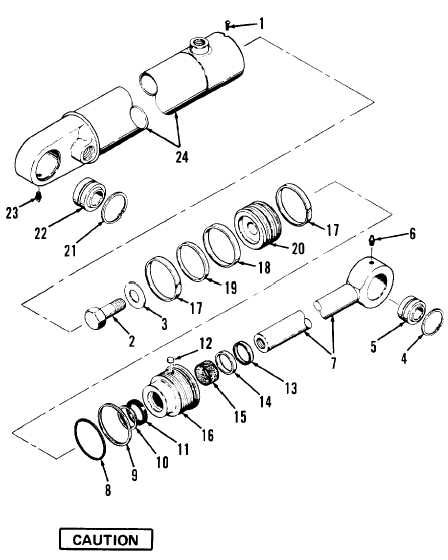
LEGEND
1.
2.
3.
4.
5.
6.
7.
8.
9.
10.
11.
12.
13.
14.
15.
16.
17.
18.
19.
20.
21.
22.
23.
24.
Screw
Capscrew
Washer
1 OF 3)
a.
b.
c.
d.
Retaining rings (2)
Bearing
Lubrication fitting
Rod
O-ring
Backup ring
Seal
Seal
Plug
Wiper
Retaining ring
Bushing
G l a n d
Wear rings (2)
Piston seal
Piston ring
Piston
Retaining rings
Bearing
Lubrication fitting
Cylinder tube
Do not over-tighten vise when performing step a below. Over-tightening
will distort cylinder tube (24).
Put steering cylinder assembly in
vise.
Remove screw (1) if present.
Using spanner wrench, unscrew gland
assembly (8 thru 16) from cylinder
tube (24).
Remove rod assembly (2 thru 7) with
gland assembly (8 thru 16) and pis-
ton assembly (17 thru 20).
4-241

