TM 5-3805-262-34
INSPECTION/REPAIR (SHEET 3 OF 4)
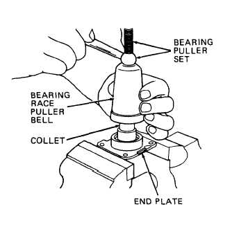
(f) Press bearing cups (83 and
84) from housing and end
plate using bearing puller
set.
(g) Remove oil seal (85) from
end plate and press in new
oil seal.
(h) Press new bearing cups (83 and
84) into housing and end
plate.
In following two steps, press
on inner diameter of bearing
cones to prevent damage to
bearings.
(i) Position stop ring (82) and shims (81) on drive end of camshaft (86).
Press on new bearing cone (80).
(j) Position stop ring (79) and shims (78) on governor end of camshaft (86).
Press on new bearing cone (77).
(k) Apply thin film of Molykote paste to surface of intermediate bearing
(4)
(5)
(6)
(76), then install intermediate bearing (76) on camshaft (86).
Inspect plungers (40) and barrels (58) for scratches, nicks, and vertical
grooves. Dip each plunger and mating barrel in clean calibrating fluid,
hold barrel vertical, and position approximately 3/4 of plunger length in
barrel. When released, plunger must slide down smoothly into barrel as
far as the stop on plunger vane. Replace plunger with barrel as an assem-
bly if any of the above conditions are seen.
Inspect delivery valves (57) for crushed or unevenly worn seats, grooved
bore, or thread damage. Inspect pistons (53) for cracks or vertical
grooves.
Insert each piston in its mating delivery valve and check free-
dom of movement. Replace delivery valve (57) and piston (53) if any of
the above conditions are seen.
Inspect control rack (48) for cracks, grooves, distortion, or chipped or
worn teeth. Repair slight grooving using abrasive cloths. Inspect thread-
ed ring (64), retainer (65), and bushings (66) for cracks or burrs. In-
stall control rack (48) and slide back and forth. Control rack must not
wobble or jam. Replace threaded ring (64), retainer (65), and bushings
(66) if control rack wobbles or jams.
3-151


