TM 5-3805-262-34
3-2. FUEL SYSTEM MAINTENANCE (CONT)
d. Fuel Injection Pump (Cont) .
REASSEMBLY (SHEET 5 OF 12)
LEGEND
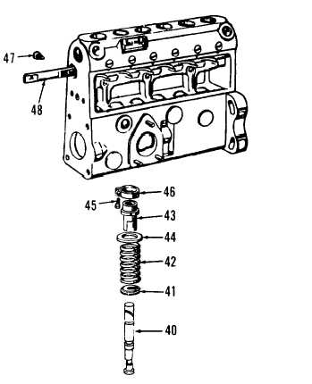
40. Plungers (6)
41. Lower seats (6)
42. Springs (6)
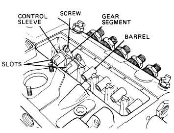
43. Control sleeves (6)
44. Upper seats (6)
45. Screws (6)
46. Gear segments (6)
47. Screw
48. Control rack
(10) Install control rack (48) and screw
(47). Position control rack at center
of travel, then tighten screw (47) to
44 to 52 lb-in.
(11) Tip injection pump housing on its
side and install control sleeves
(a)
(b)
(c)
(d)
(e)
(43) :
Install screw (45) in gear segment
(46). Do not tighten screw.
Slide gear segment (46) onto control
sleeve (43).
Position control sleeve (43) adjusting slots out, and screw (45) at top
right. Then slide control sleeve (43) with gear segment (46) onto bar-
rel.
Center gear segment (46) teeth
on control rack, and mesh gear
segment with control rack.
Rotate control sleeve
(43) slot outward as
shown. If original con-
trol sleeve and gear seg-
ment are installed, ro-
tate control sleeve to
aline scribe mark made
during disassembly. Then
tighten screw (45) to 26
to 28 lb-in.
3-156