TM 5-3805-262-34
INSPECTION, TESTING, AND REPAIR (SHEET 2 OF 7)
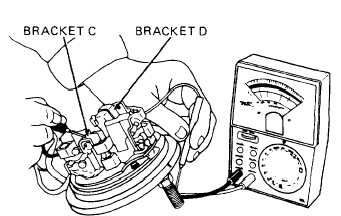
(3) Hold multimeter red lead on
plate assembly terminal stud,
black lead on bracket C. Note
multimeter indication. Move
black lead to bracket D and
note multimeter indication.
Multimeter should indicate
open circuit (multimeter
pointer should not move).
b. Inspect springs (18 and 66) for
cracks, broken or missing
coils, or permanent set.
c. Inspect drive assembly (44) for worn or damaged splines. Check teeth for
chips, cracks, and wear. Slide drive assembly onto armature (27) shaft and
check that it moves freely. Replace drive assembly (44) if any of the above
conditions are seen.
d. Inspect field coil (37) for damaged windings or distortion. Inspect field coil
leads for broken wire strands. Check terminal stud (39) for thread damage. If
thread damage is seen remove field coil from field frame, unsolder defective
terminal stud (39), and solder new terminal stud onto field coil. Replace
field coil if any of the above conditions are seen, or if field coil does not
pass the following tests:
(1)
(2)
(3)
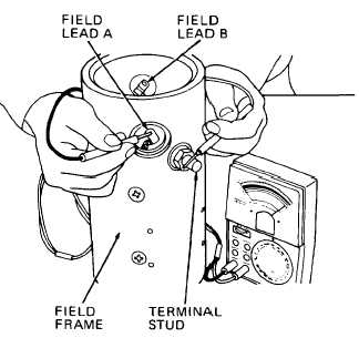
Hold multimeter red lead on
terminal stud, black lead on
field lead A. Note multimeter
indication. Move black lead to
field lead B and note multi-
meter indication. Multimeter
should indicate continuity
(multimeter pointer should
move) .
Hold multimeter red lead on
terminal stud, black lead on
field frame. Multimeter should
indicate open circuit (multi-
meter pointer should not
move).
Hold multimeter red lead on
field lead A, black lead on
field lead B. Multimeter
should indicate continuity
(multimeter pointer should
move).
3-235