TM 5-3805-262-34
3-21. CHECKS AND ADJUSTMENTS AND FLOWMETER TESTS (CONT)
d. Circuit Relief Valves Pressure Setting Check and Adjustment (SHEET 1 OF 3).
This task covers checking and adjustment of control valve assembly circuit relief
valves pressure settings. There are four circuit relief valves used in the control
valve assembly. These are used to protect the clam and bucket circuits.
TOOLS: No. 1 Common Organizational Maintenance Tool Kit
Fixed open end wrench set
Slip joint pliers
Drill, 1/2 inch capacity
Drill bit, 1/4 inch diameter
Drive pin punch, 1/8 inch point
Hand pump (FSCM 45225 PN CAS-10090)
Fitting kit (FSCM 45225 PN CAS-10111)
Adjusting tool (fabricate from 1/2 inch Allen wrench, 1-1/2 inches long
with a 3/8 inch diameter hole drilled completely through it)
Pipe plug
MATERIALS/PARTS: Clean cloths (Appendix C, item 1)
Cleaning solvent P-D-680 (Appendix C, item 2)
Expansion plug (FSCM 10988 PN 41-14)
NOTE
PRELIMINARY PROCEDURE: Control levers operated several times in both di-
rections to relieve hydraulic pressure, front access door unlocked and
open, and hydraulic reservoir fill cap loosened.
Hydraulic system pressure is over
2000 psi and hydraulic reservoir
is pressurized with compressed
air.
Before loosening or
disconnecting any hydraulic
hoses, lines, or fittings,
operate all hydraulic control
levers to relieve hydraulic
system pressure. Failure to do so
could cause serious injury or
death. If you are injured obtain
medical assistance immediately.
NOTE
Ensure that hand pump is full of
hydraulic oil and that tempera-
ture of hand pump hydraulic oil
is between 70 to 80 degrees F.
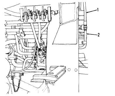
(1) Disconnect line between cylinder and control valve assembly in the cir-
cuit in which the circuit relief valve is to be checked:
NOTE
Clean all dirt and grease from hose and tube fittings before discon-
necting them.
3-624


