TM 5-3805-262-34
DISASSEMBLY (SHEET 2 OF 3)
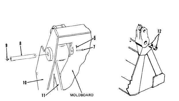
g. Remove two pins (8) from blade assembly (10) and clam assembly (11) using
hammer and 1/2 inch diameter by 9 inches long rod. Lay rod flat on moldboard
of blade assembly , slide rod against pin, then drive pin outward.
When using chain hoist to remove or install parts, be sure chain hoist
is securely fastened to part and that all slack in chain is taken up.
Failure to do so could cause serious injury due to part falling on you.
If you are injured by falling equipment, obtain medical aid immediately.
h. Using chain hoist, raise and move blade assembly (10) rearward until it clears
clam assembly (11). Lower blade assembly to ground.
NOTE
Don’t perform following steps unless inspection indicates bushings (12
and 13) require replacement.
LEGEND
6.
7.
8.
9.
10.
11.
12.
Cotter pins (2)
Clevis pins (2)
Pins (2)
Lubrication fittings (2)
Blade assembly
Clam assembly
Bushings (4)
i. If necessary for replacement, remove four bushings (12) from clam assembly
(11). Use hammer and 3/8 inch drive pin punch to drive bushings outward from
clam assembly. Put drive pin punch through one side of clam assembly and drive
bushing outward. Drive bushing evenly from bore.
3-783


