
TM 5-3805-291-23-1
TROUBLESHOOTING WITH A DIAGNOSTIC CODE - CONTINUED
0009 00
Table 4. Implement Control - Continued.
(MID 082)
MALFUNCTION
TEST OR INSPECTION
CORRECTIVE ACTION
427-C1664
N OT E
0487 03
The following test procedure may create other diagnostic codes. Ignore these
created diagnostic codes and clear these diagnostic codes when original diagnos-
tic code is corrected.
Ensure diagnostic code is active.
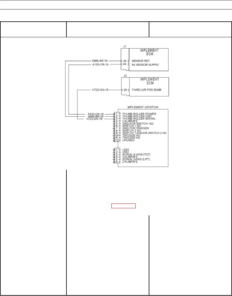
figuration receives system voltage and the other receives 8 volts.
1. Check for power at sensor.
(a) Do not disconnect wiring harness
connector from sensor.
(b) Turn engine start and battery
disconnect switches to ON position
(TM 5-3805-291-10).
(c) At wiring harness connector for
1. If voltage is system voltage, go to Test 2.
sensor, measure voltage from
2. If voltage is not system voltage, +battery
contact 1 to contact 2.
circuit in working harness has failed.
Replace wiring harness in question (WP
0195 00 thru WP 0201 00).