
TM 5-3805-292-23
0007
HYDROSTATIC SYSTEM CONTINUED
Checking Circuit Relief Valve Pressure - Continued
0007
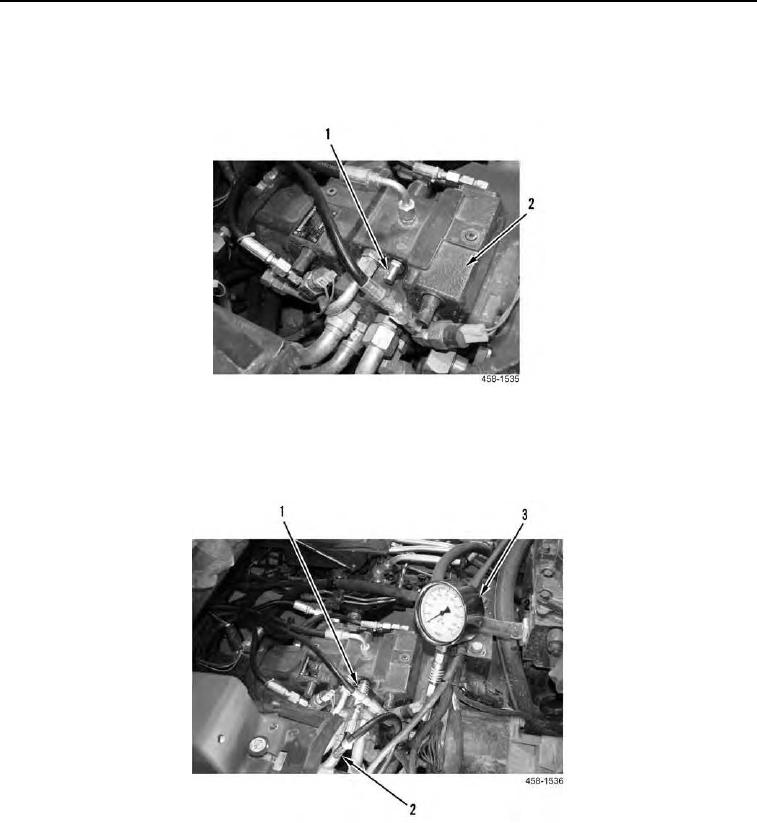
7. Install male test quick disconnect fitting (Figure 13, Item 1) in hydrostatic pump (Figure 13, Item 2).
Figure 13. Male Test Quick Disconnect.
0007
8. Connect hose (Figure 14, Item 2) and test gauge (Figure 14, Item 3) to the male test quick disconnect
(Figure 14, Item 1).
Figure 14. Test Gauge.
0007
0007-16