
TM 5-3805-292-23
0007
HYDROSTATIC SYSTEM CONTINUED
Checking Circuit Relief Valve Pressure - Continued
0007
3. Tilt ROPS (WP 0134).
N OT E
Tag hoses to ensure correct installation.
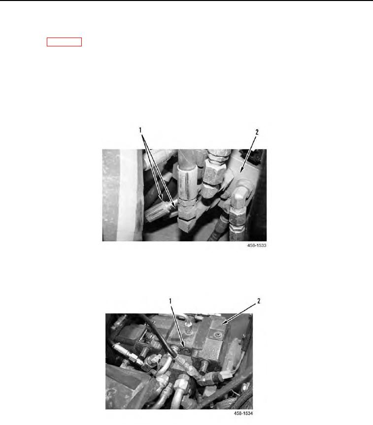
4. Disconnect two brake supply hoses (Figure 11, Item 1) from brake valve (Figure 11, Item 2).
5. Plug two hoses (Figure 11, Item 1) and cap ports in brake valve (Figure 11, Item 2) for hoses
(Figure 11, Item 1).
Figure 11. Brake Valve.
0007
6. Remove the left forward diagnostic plug (Figure 12, Item 1) from the hydrostatic pump (Figure 12, Item 2).
Figure 12. Diagnostic Plug.
0007