
TM 5-3805-292-23
0007
HYDROSTATIC SYSTEM CONTINUED
Checking Circuit Relief Valve Pressure - Continued
0007
19. Remove jumper from seat switch and connect seat switch.
20. Remove all testing equipment.
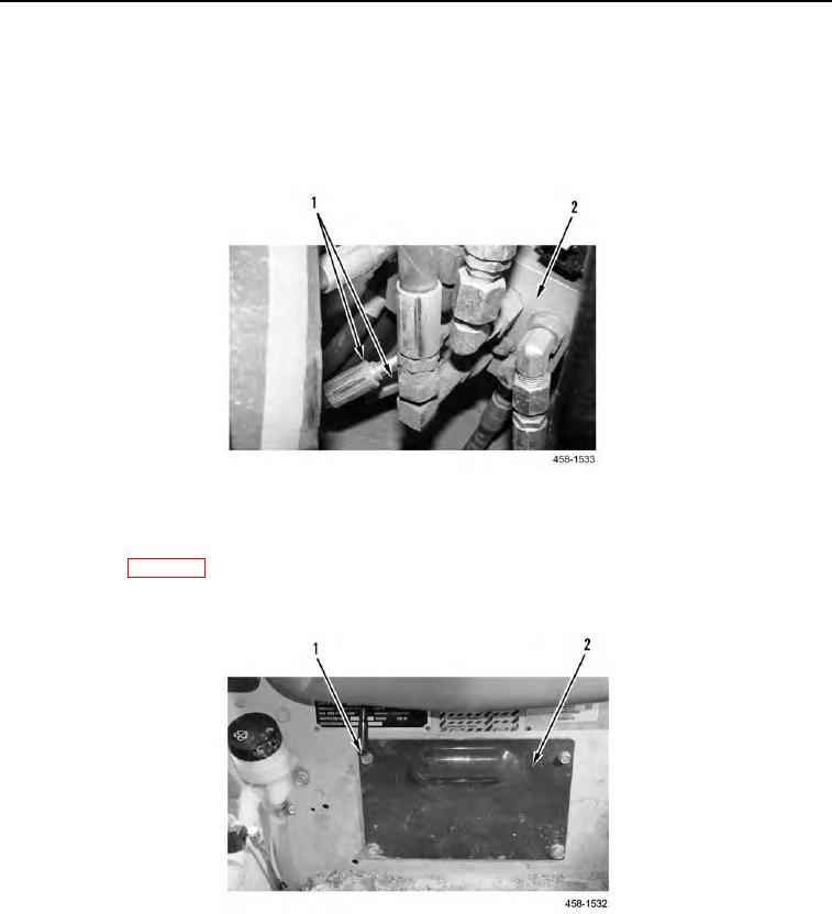
21. Reconnect hoses (Figure 18, Item 1) to brake valve (Figure 18, Item 2).
Figure 18. Brake Valve.
0007
22. Remove supports and lower machine to ground.
23. Close ROPS (WP 0134).
24. Install plate (Figure 19, Item 2) and four bolts (Figure 19, Item 1).
Figure 19. Access Plate.
0007
END OF TASK