
TM 5-3805-292-23
0078
INSTALLATION CONTINUED
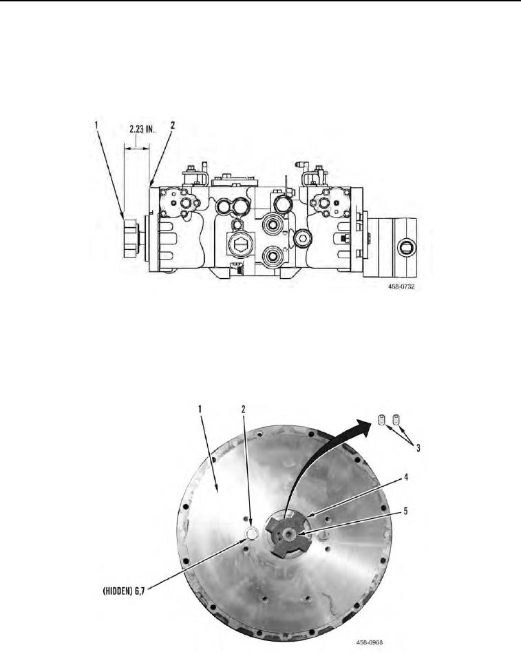
N OT E
The distance from the outer face of the coupling should not extend more than 2.23 in.
(56.5 mm) from the tandem pump mounting flange.
2. Install coupling (Figure 5, Item 1) on tandem pump (Figure 5, Item 2).
Figure 5. Coupling Dimension.
0078
3. Tighten two set screws (Figure 6, Item 3) on coupling (Figure 6, Item 4) to 37 to 40 lb-ft (50 to 54 Nm).
4. Install plate (Figure 6, Item 1), two nuts (Figure 6, Item 7), four washers (Figure 6, Item 6), and two bolts (Fig-
ure 6, Item 2) on tandem pump (Figure 6, Item 5).
5. Tighten two bolts (Figure 6, Item 2) to 35 to 45 lb-ft (47 to 61 Nm).
Figure 6. Plate and Coupling.
0078