
TM 5-3805-292-23
0078
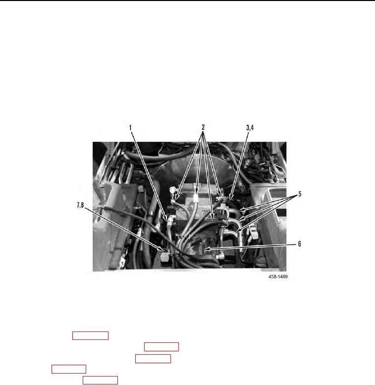
INSTALLATION CONTINUED
10. Connect lines (Figure 8, Items 4 and 8) to tandem pump (Figure 8, Item 6) and tighten clamps (Figure 8, Items
3 and 7).
11. Connect four lines (Figure 8, Item 5) to tandem pump (Figure 8, Item 6).
N OT E
One line is connected on bottom of tandem pump.
12. Connect five lines (Figure 8, Item 2) to tandem pump (Figure 8, Item 6).
13. Connect line (Figure 8, Item 1) to tandem pump (Figure 8, Item 6).
`
Figure 8. Tandem Pump.
0078
END OF TASK
FOLLOW-ON TASKS
00078
1. Install gear pump (WP 0088).
2. Install hydraulic oil temperature sender (WP 0162).
3.
Install backup alarm pressure switch (WP 0140).
4.
Install seat (WP 0126).
5.
Fill hydraulic system (WP 0009).
6.
Verify correct operation of machine (TM 5-3805-292-10).
END OF TASK
END OF WORK PACKAGE