
TM 5-3805-292-23
0089
DISASSEMBLY CONTINUED
WARN I N G
Springs may have significant tension. Use extreme caution when removing springs.
Springs under tension can act as projectiles when released. Failure to follow this warning
may result in injury to personnel.
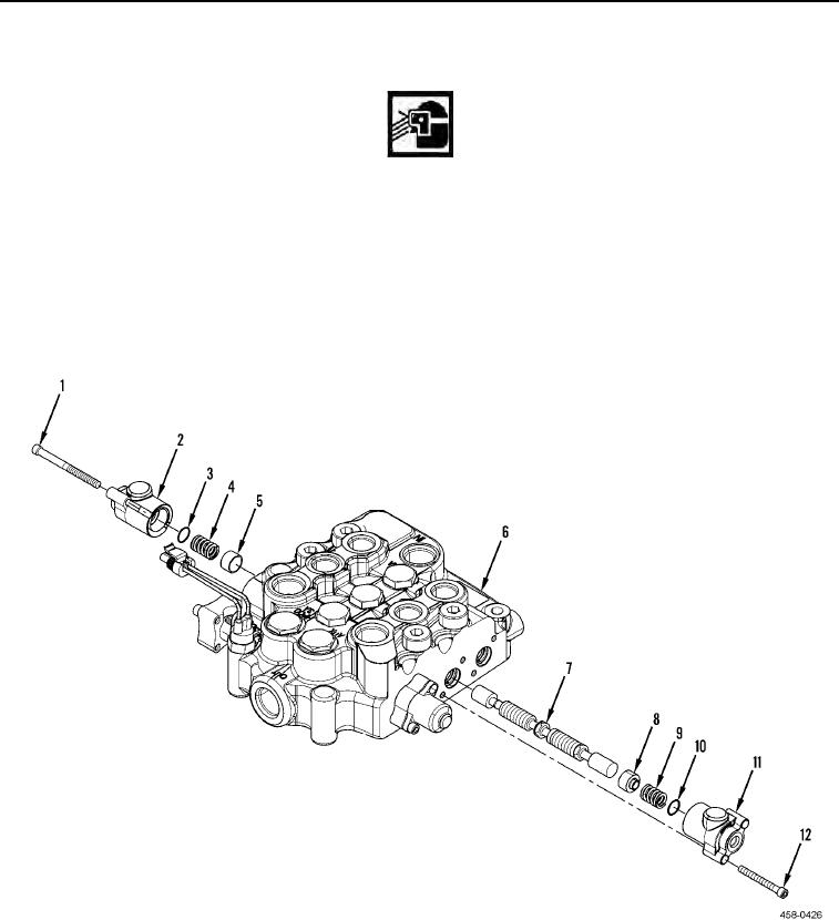
7. Remove two bolts (Figure 5, Item 12), cap (Figure 5, Item 11), O-ring (Figure 5, Item 10), spring (Figure 5, Item
9), and plunger (Figure 5, Item 8) from main hydraulic valve (Figure 5, Item 6). Discard O-ring.
8. Remove two bolts (Figure 5, Item 1), cap (Figure 5, Item 2), O-ring (Figure 5, Item 3), spring (Figure 5, Item 4),
and plunger (Figure 5, Item 5) from main hydraulic valve (Figure 5, Item 6). Discard O-ring.
9. Remove bucket spool (Figure 5, Item 7) from main hydraulic valve (Figure 5, Item 6).
Figure 5. Bucket Spool.
0089
10. Remove switch (Figure 6, Item 18) and O-ring (Figure 6, Item 17) from cap (Figure 6, Item 4). Discard O-ring.
11. Remove O-ring (Figure 6, Item 2), and seal (Figure 6, Item 3) from cap (Figure 6, Item 4). Discard O-ring and
seal.