
TM 5-3805-292-23
0089
DISASSEMBLY
00089
N OT E
Note location, arrangement, and orientation of all components to aid in installation.
Disassemble main hydraulic valve on a clean, flat work surface.
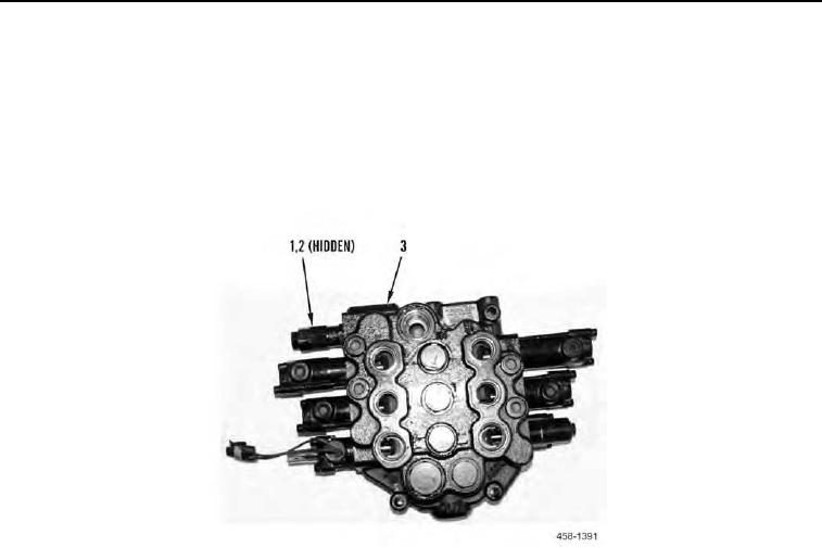
1. Remove pressure relief valve (Figure 2, Item 1) and O-ring (Figure 2, Item 2) from main hydraulic valve (Figure
2, Item 3). Discard O-ring.
Figure 2. Main Hydraulic Valve.
0089