
TM 5-3805-292-23
0089
DISASSEMBLY CONTINUED
WARN I N G
Springs may have significant tension. Use extreme caution when removing springs.
Springs under tension can act as projectiles when released. Failure to follow this warning
may result in injury to personnel.
N OT E
Loosen bolts evenly.
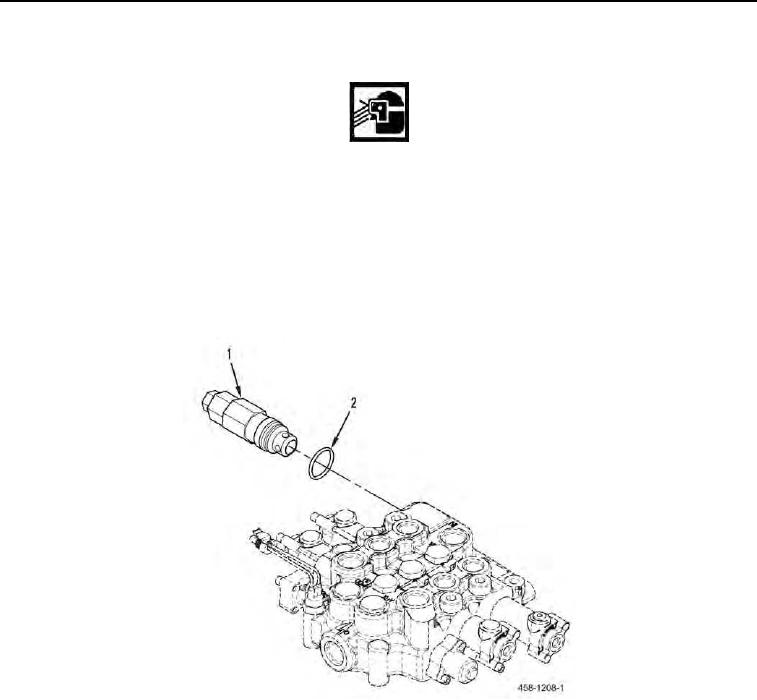
2. Remove pressure relief valve (Figure 3, Item 1) and O-ring (Figure 3, Item 2) from main hydraulic control valve.
Discard O-ring.
Figure 3. Pressure Relief Valve.
0089