
TM 5-3805-292-23
0089
REMOVAL
00089
N OT E
Tag all hoses, lines, fittings, and wiring harnesses to aid in installation.
Use a container to catch any fluid that maydrain from hoses or system. Dispose of fluid
IAW local policy and ordinances. Ensure all spills are cleaned up.
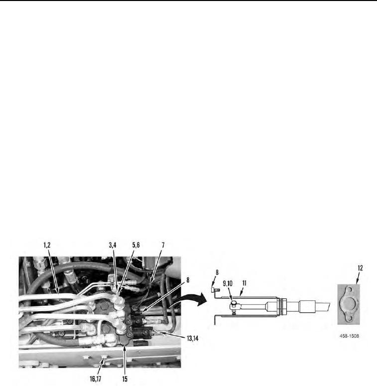
1. Disconnect electrical connector (Figure 1, Item 7).
2. Remove clip (Figure 1, Item 9), pin (Figure 1, Item 10), two bolts (Figure 1, Item 8), and bracket (Figure 1, Item
11) and plate (Figure 1, Item 12) from main hydraulic valve (Figure 1, Item 15).
3. Remove locknut (Figure 1, Item 3), washer (Figure 1, Item 4), bolt (Figure 1, Item 6), and bracket (Figure 1,
Item 5) from main hydraulic valve (Figure 1, Item 15). Discard locknut.
4. Remove nine lines (Figure 1, Item 1) and fittings (Figure 1, Item 2) from main hydraulic valve (Figure 1,
Item 15).
5. Remove three hoses (Figure 1, Item 13) and fittings (Figure 1, Item 14) from main hydraulic valve (Figure 1,
Item 15).
N OT E
Main hydraulic valve weighs 40 lb (18 kg).
6. Remove two bolts (Figure 1, Item 16), four washers (Figure 1, Item 17), and main hydraulic valve (Figure 1,
Item 15) from machine.
Figure 1. Main Hydraulic Valve.
0089
END OF TASK