
12
TM 5-3805-292-23
FIELD MAINTENANCE
-
SEAT ASSEMBLY MAINTENANCE
012
6
REMOVAL, CLEANING AND INSPECTION, INSTALLATION
INITIAL SETUP
References
Tools and Special Tools
0
0
Tool Kit, General Mechanic's (WP 0178, Item
TM 5-3805-292-23P, Figure 62
0
33)
0
Equipment Conditions
0
Wooden Block
0
Engine off (TM 5-3805-292-10)
0
Materials/Parts
ROPS tilted (WP 0134)
0
0
Cleaning Compound, Solvent, Type III (WP
Estimated Time to Complete
0179, Item 3)
0
0
1.0 Hr
Rag, Wiping (WP 0179, Item 19)
0
0
Tag, Marker (WP 0179, Item 30)
0
REMOVAL
000126
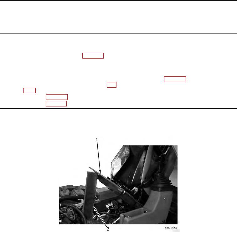
1. Tilt seat assembly (Figure 1, Item 1) forward and support seat assembly with wooden block (Figure 1, Item 2).
Figure 1. Tilting and Blocking Seat Assembly.
0126