• Home
  • Download PDF
  • Order CD-ROM
  • Order in Print
Figure 3. Electrical Connector and Buckle.
Figure 5. Seat Support.

Field Maintenance Manual For M400T And M400W
Page Navigation
  835    836    837    838    839  840  841    842    843    844    845  
img
.
TM 5-3805-292-23
0126
REMOVAL CONTINUED
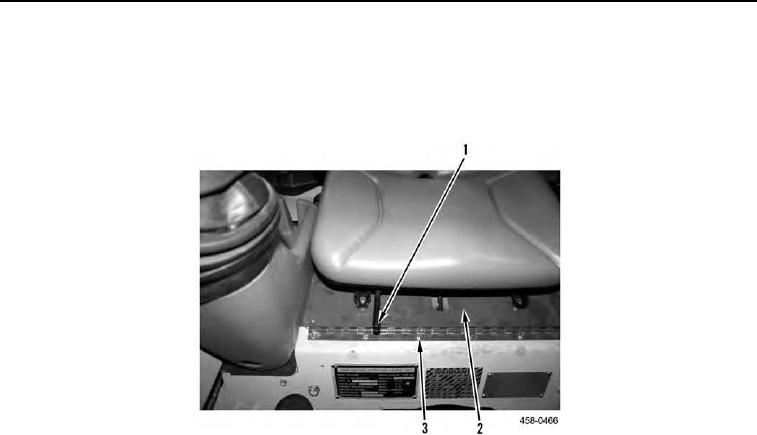
8. Remove wooden block and lower seat assembly (Figure 4, Item 2).
9. Use seat forward/aft adjustment lever (Figure 4, Item 1) to adjust seat position fully back.
10. Remove six mounting bolts (Figure 4, Item 3) from seat assembly (Figure 4, Item 2).
Figure 4. Seat Assembly Mounting.
0126
0126-4


Privacy Statement
Press Release
Contact

© Copyright Integrated Publishing, Inc.. All Rights Reserved.