• Home
  • Download PDF
  • Order CD-ROM
  • Order in Print
Figure 2. Electrical Connector and Support Strut.
Figure 4. Seat Assembly Mounting.

Field Maintenance Manual For M400T And M400W
Page Navigation
  834    835    836    837    838  839  840    841    842    843    844  
img
.
TM 5-3805-292-23
0126
REMOVAL CONTINUED
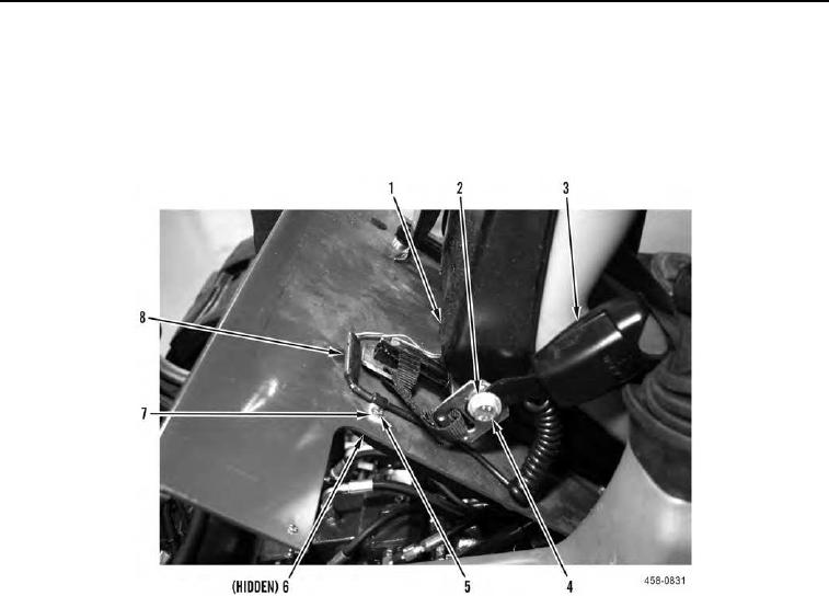
4. Disconnect electrical connector (Figure 3, Item 8).
5. Remove nut (Figure 3, Item 6) and bolt (Figure 3, Item 5) from clamp (Figure 3, Item 7).
6. Remove bolt (Figure 3, Item 4) and washer (Figure 3, Item 2) from seat assembly (Figure 3, Item 1).
7. Remove buckle (Figure 3, Item 3) from machine.
Figure 3. Electrical Connector and Buckle.
0126
0126-3


Privacy Statement
Press Release
Contact

© Copyright Integrated Publishing, Inc.. All Rights Reserved.