• Home
  • Download PDF
  • Order CD-ROM
  • Order in Print
Figure 4. Seat Assembly Mounting.
Figure 7. Seat Mount.

Field Maintenance Manual For M400T And M400W
Page Navigation
  836    837    838    839    840  841  842    843    844    845    846  
img
.
TM 5-3805-292-23
0126
REMOVAL CONTINUED
11. Remove seat support (Figure 5, Item 2) and seat assembly (Figure 5, Item 1) from machine.
Figure 5. Seat Support.
0126
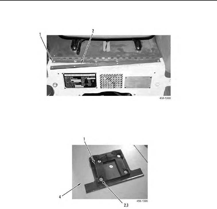
12. Remove foam (Figure 6, Item 1), five fasteners (Figure 6, Item 2), and washers (Figure 6, Item 3) from hinge
plate (Figure 6, Item 4).
Figure 6. Foam and Fasteners.
0126
0126-5


Privacy Statement
Press Release
Contact

© Copyright Integrated Publishing, Inc.. All Rights Reserved.