• Home
  • Download PDF
  • Order CD-ROM
  • Order in Print
SEAT ASSEMBLY MAINTENANCE
Figure 3. Electrical Connector and Buckle.

Field Maintenance Manual For M400T And M400W
Page Navigation
  833    834    835    836    837  838  839    840    841    842    843  
img
.
TM 5-3805-292-23
0126
REMOVAL CONTINUED
N OT E
Tag and identify all wires and connectors to aid in installation.
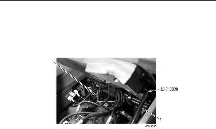
2. Disconnect electrical connector (Figure 2, Item 1).
3. Remove nuts (Figure 2, Item 2) and ball studs (Figure 2, Item 3) from both ends of seat assembly support strut
(Figure 2, Item 4).
Figure 2. Electrical Connector and Support Strut.
0126
0126-2


Privacy Statement
Press Release
Contact

© Copyright Integrated Publishing, Inc.. All Rights Reserved.