
TM 5-3805-292-23
0126
INSTALLATION CONTINUED
N OT E
Install wires as tagged.
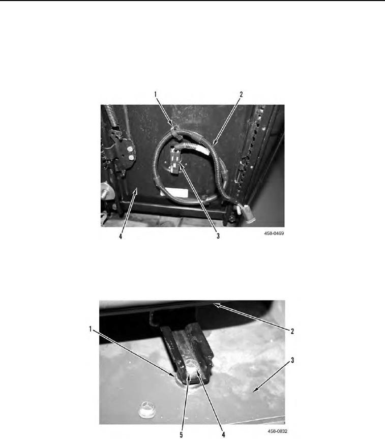
2. Connect electrical connector (Figure 10, Item 3) and route wiring harness (Figure 10, Item 2) through two
clamps (Figure 10, Item 1) on seat (Figure 10, Item 4).
Figure 10. Wiring Harness.
0126
3. Position seat (Figure 11, Item 2) on hinge plate (Figure 11, Item 3) and install eight spacers (Figure 11, Item 1),
four washers (Figure 11, Item 5), and nuts (Figure 11, Item 4).
Figure 11. Seat Mount.
0126