
TM 5-3805-292-23
0126
INSTALLATION CONTINUED
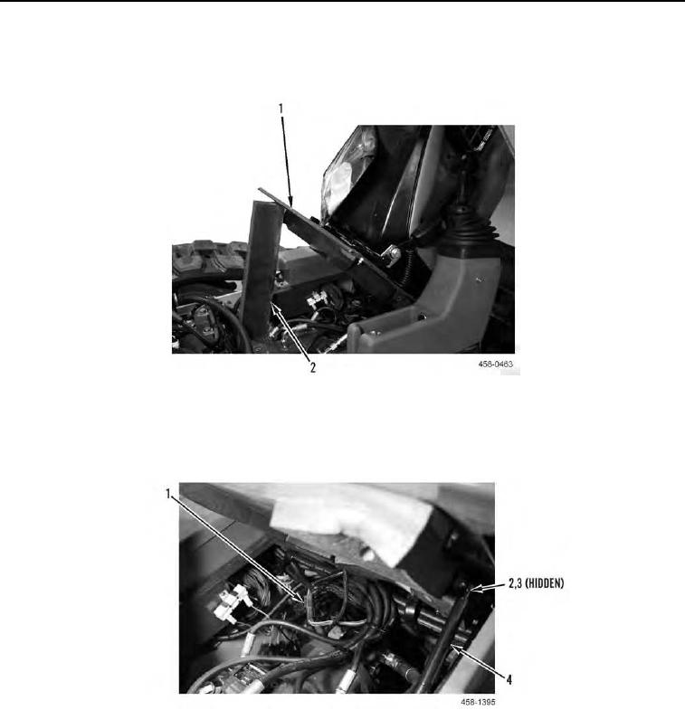
8. Adjust seat fully forward and tilt seat assembly (Figure 14, Item 1) forward and support seat assembly with
wooden block (Figure 14, Item 2).
Figure 14. Tilting and Blocking Seat Assembly.
0126
9. Install ball stud (Figure 15, Item 3) and nut (Figure 15, Item 2) on both ends of seat assembly support strut
(Figure 15, Item 4).
10. Connect electrical connector (Figure 15, Item 1).
Figure 15. Electrical Connector and Support Strut.
0126