
TM 5-3805-292-23
0127
REMOVAL CONTINUED
5. Remove bolt (Figure 2, Item 6), washer (Figure 2, Item 5), nut (Figure 2, Item 4), spacer (Figure 2, Item 1), and
clamp (Figure 2, Item 2) from control rod (Figure 2, item 3).
Figure 2. Throttle Control Rod Retaining Clamp.
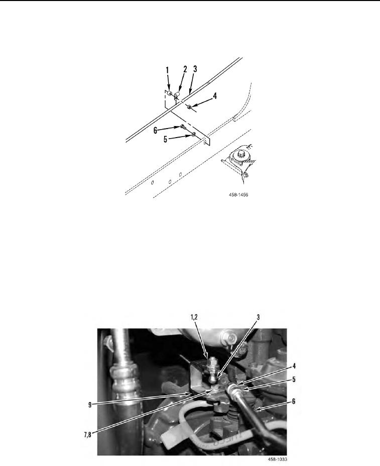
0127
6. Pull back on sleeve (Figure 3, Item 4) and remove control rod (Figure 3, Item 6) from ball stud (Figure 3,
Item 3).
7. Remove sleeve (Figure 3, Item 4) and jam nut (Figure 3, Item 5) from control rod (Figure 3, Item 6).
8. Remove nut (Figure 3, Item 1), lockwasher (Figure 3, Item 2), and ball stud (Figure 3, Item 3) from bracket
(Figure 3, Item 9). Discard lockwasher.
9. Remove two bolts (Figure 3, Item 7), lockwashers (Figure 3, Item 8), and bracket (Figure 3, Item 9) from
engine. Discard lockwashers.
Figure 3. Actuator-to-Engine Control Rod (Rear).
0127