Home
Download PDF
Order CD-ROM
Order in Print
Figure 3. Locking Lever.
PALLET FORKS REPAIR - Continued
Field Maintenance Manual For M400T And M400W
Page Navigation
1106
1107
1108
1109
1110
1111
1112
1113
1114
1115
1116
TM
5-3805-292-23
0170
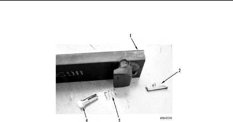
DISASSEMBLY
CONTINUED
5.
Remove
pin
(Figure
5,
Item
4),
spring
(Figure
5,
Item
3),
and
locking
lever
(Figure
5,
Item
2)
from
tine
(Figure
5,
Item
1).
Figure 5.
Locking
Lever
Assembly.
0170
END
OF
TASK
0170-4