• Home
  • Download PDF
  • Order CD-ROM
  • Order in Print
Figure 2. Tine Removal.
Figure 5. Locking Lever Assembly.

Field Maintenance Manual For M400T And M400W
Page Navigation
  1105    1106    1107    1108    1109  1110  1111    1112    1113    1114    1115  
img
.
TM 5-3805-292-23
0170
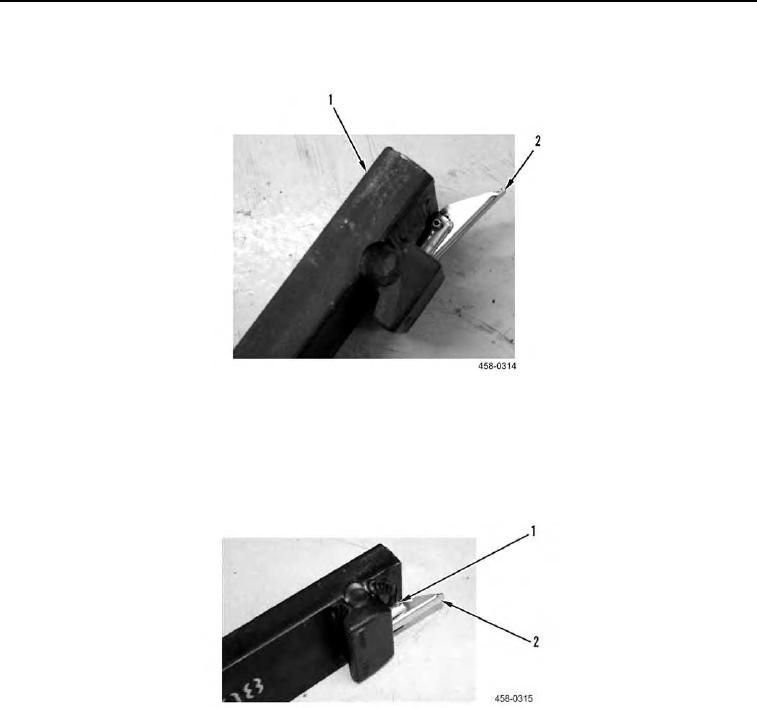
DISASSEMBLY CONTINUED
3. Turn locking lever (Figure 3, Item 2) assembly 90 degrees and lay tine (Figure 3, Item 1) flat.
Figure 3. Locking Lever.
0170
N OT E
Components are lightly spring-loaded.
4. Remove roll pin (Figure 4, Item 1) from locking lever assembly (Figure 4, Item 2).
Figure 4. Roll Pin Removal.
0170
0170-3


Privacy Statement
Press Release
Contact

© Copyright Integrated Publishing, Inc.. All Rights Reserved.