
TM 5-3805-298-23-2
0155
Table 1. Kickout System Will Not Operate or Operates Improperly Continued.
0155
MALFUNCTION
TEST OR INSPECTION
CORRECTIVE ACTION
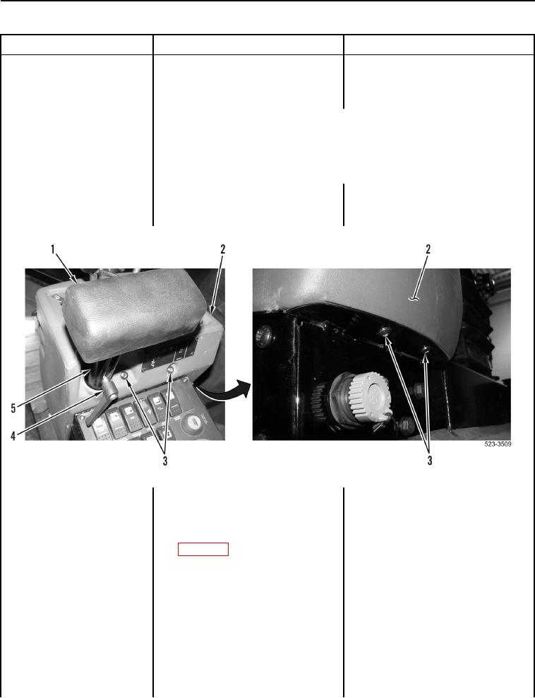
3. Remove control lever (Figure 10,
Kickout System Will Not
Item 4) and armrest cushion
Operate or Operates
(Figure 10, Item 1) from support
Improperly - Continued
post (Figure 10, Item 5).
NOTE
Two bolts are located at top rear and two bolts are located at bottom front
of operator console.
4. Remove four bolts (Figure 10,
Item 3) and operator console cover
(Figure 10, Item 2) from machine.
Figure 10. Arm Rest and Operator Console Cover.
0155
5. Disconnect connector C-C22 from
pilot valve connector (WP 0012,
Figure 232).
6. Using digital multimeter
Resistance 5.0 Ohms or Less
(WP 0174), measure resistance
Proceed to step 7.
between connector C-C22
Resistance Greater Than 5.0 Ohms
terminal 6 (WP 0012, Figure 232)
Replace lower cab wiring harness
and ground.
(WP 0291).
Proceed to Test Step 60.