• Home
  • Download PDF
  • Order CD-ROM
  • Order in Print
Figure 4. Engine Control Wiring Harness.
Figure 6. Inlet Manifold.

Field Maintenance Manual For 924H Wheel Loader -2 Page Navigation
  774    775    776    777    778  779  780    781    782    783    784  
img
.
TM 5-3805-298-23-2
0196
REMOVAL CONTINUED
000196
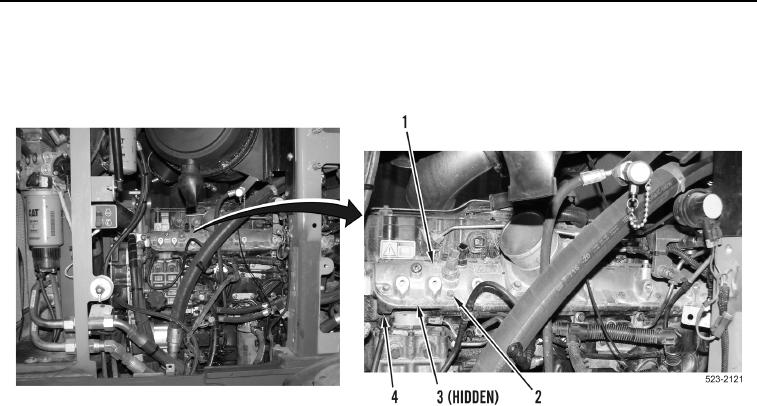
15. Remove 15 bolts (Figure 5, Item 2), inlet manifold (Figure 5, Item 1) and gasket (Figure 5, Item 3) from engine
(Figure 5, Item 4). Discard gasket.
Figure 5. Inlet Manifold Bolts and Inlet Manifold.
0196
END OF TASK
0196-5


Privacy Statement
Press Release
Contact

© Copyright Integrated Publishing, Inc.. All Rights Reserved.