
TM 5-3805-298-23-2
0196
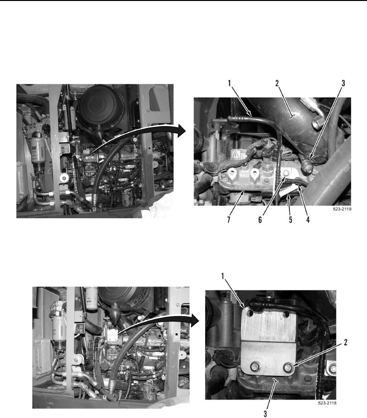
INSTALLATION CONTINUED
8. Install bracket (Figure 10, Item 5) and bolt (Figure 10, Item 6) on inlet manifold (Figure 10, Item 7).
9. Install fuel tubes (Figure 10, Item 1) on clips (Figure 10, Item 4).
10. Install intake tube (Figure 10, Item 2) on inlet manifold (Figure 10, Item 7) and tighten clamp (Figure 10,
Item 3).
Figure 10. Intake Tube and Fuel Line Bracket.
0196
11. Install bracket (Figure 11, Item 1) and two bolts (Figure 11, Item 2) on inlet manifold (Figure 11, Item 3).
Figure 11. Bracket.
0196