
TM 5-3805-298-23-2
0196
INSTALLATION CONTINUED
NOTE
Route wiring harness and install all wiring harness connectors as noted during removal.
Install tiedown straps as noted during removal.
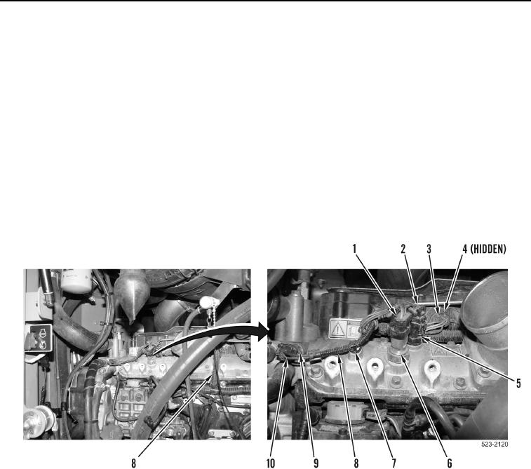
3. Route engine control wiring harness (Figure 9, Item 8) and install new tiedown straps (Figure 9, Item 7).
4. Connect engine control wiring harness connector (Figure 9, Item 3) on injector1 and 2 wiring harness
connector (Figure 9, Item 4).
5. Connect engine control wiring harness connector (Figure 9, Item 2) on air intake temperature sensor
(Figure 9, Item 5).
6. Connect engine control wiring harness connector (Figure 9, Item 1) on air pressure sensor (Figure 9, Item 6).
7. Connect engine control wiring harness connector (Figure 9, Item 10) on coolant temperature sensor
(Figure 9, Item 9).
Figure 9. Engine Control Wiring Harness.
0196