• Home
  • Download PDF
  • Order CD-ROM
  • Order in Print
Figure 6. Inlet Manifold.
Figure 9. Engine Control Wiring Harness.

Field Maintenance Manual For 924H Wheel Loader -2 Page Navigation
  776    777    778    779    780  781  782    783    784    785    786  
img
.
TM 5-3805-298-23-2
0196
INSTALLATION
000196
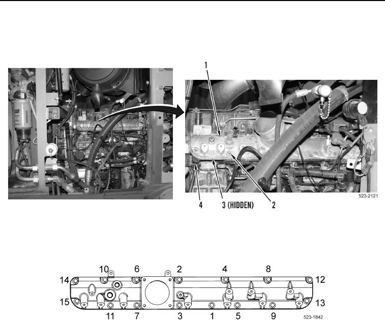
1. Install new gasket (Figure 7, Item 3), inlet manifold (Figure 7, Item 1), and 15 bolts (Figure 7, Item 2) on engine
(Figure 7, Item 4).
Figure 7. Inlet Manifold Bolts and Inlet Manifold.
0196
2. Tighten 15 bolts in sequence shown in (Figure 8) to 192 lb.-in. (22 Nm).
Figure 8. Torque Sequence.
0196
0196-7


Privacy Statement
Press Release
Contact

© Copyright Integrated Publishing, Inc.. All Rights Reserved.