
TM 5-3805-298-23-2
0196
INSTALLATION CONTINUED
NOTE
Remove caps or plugs from hoses, tube, and open ports.
Route hoses and tube as noted during removal.
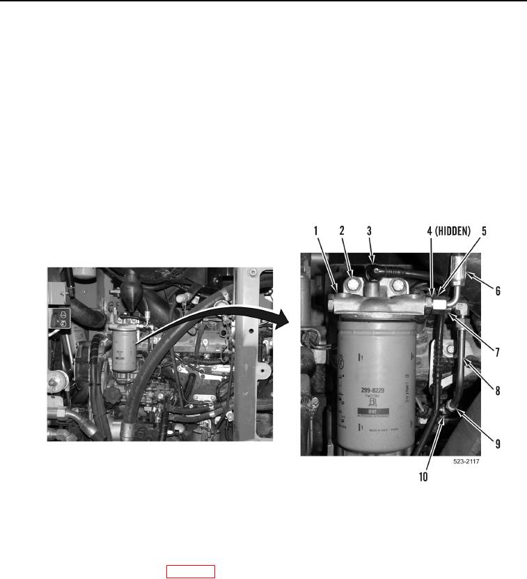
12. Install secondary fuel filter base (Figure 12, Item 1) and two bolts (Figure 12, Item 2) on machine.
13. Connect hose (Figure 12, Item 3) on secondary fuel filter base (Figure 12, Item 1).
14. Rotate tube (Figure 12, Item 8) up to secondary fuel filter base (Figure 12, Item 1) and tighten tube nut
(Figure 12, Item 7).
15. Tighten tube nut (Figure 12, Item 9) on elbow fitting (Figure 12, Item 10).
16. Install new O-ring (Figure 12, Item 4), hose (Figure 12, Item 6), and tube nut (Figure 12, Item 5) on secondary
fuel filter base (Figure 12, Item 1).
Figure 12. Secondary Fuel Filter Base.
0196
END OF TASK
FOLLOW-ON TASKS
000196
1. Install crankcase breather base (WP 0189).
2. Install engine ECM and bracket (WP 0265).
3. Prime fuel system (TM 5-3805-298-10).
4. Verify correct operation of machine (TM 5-3805-298-10).
END OF TASK
END OF WORK PACKAGE