
TM 5-3805-298-23-4
0379
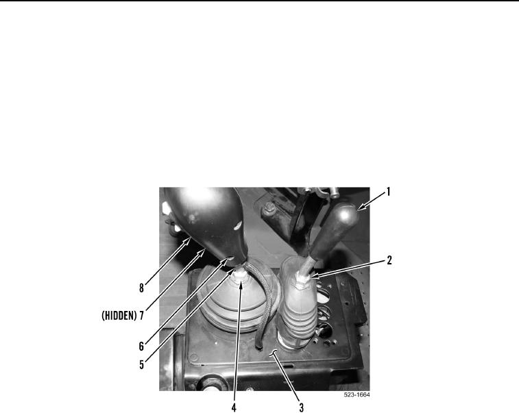
REMOVAL CONTINUED
NOTE
Note location and orientation of control handles to aid installation.
4. Loosen jam nut (Figure 3, Item 2) and remove clamshell control handle (Figure 3, Item 1) from operator
console (Figure 3, Item 3).
5. Remove two allen screws (Figure 3, Items 6 and 7) and directional and downshift control handle (Figure 3,
Item 8) from control rod (Figure 3, Item 5). Position directional and downshift control handle aside.
6. Loosen jam nut (Figure 3, Item 4) and remove control rod (Figure 3, Item 5) from operator console
(Figure 3, Item 3).
Figure 3. Control Handles.
0379