
TM 5-3805-298-23-4
0379
REMOVAL CONTINUED
NOTE
Directional and downshift switches wiring harness has two tiedown straps holding it to pilot
valve assembly. Remove ONLY the tiedown strap on bottom side of pilot valve assembly.
Tiedown strap on top side of pilot valve will ensure that directional and downshift switches
wiring harness is installed in proper location.
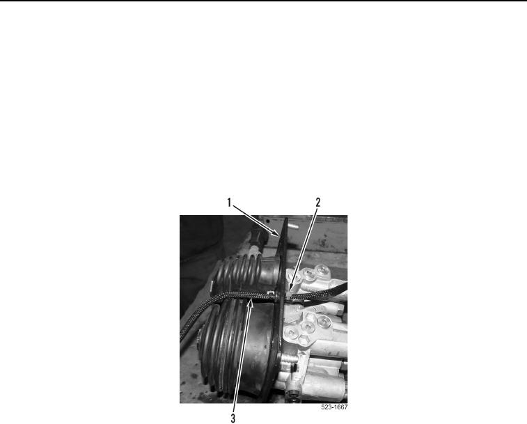
13. Remove tiedown strap (Figure 6, Item 2) from directional and downshift switches wiring harness
(Figure 6, Item 3).
14. Remove directional and downshift switches wiring harness (Figure 6, Item 3) from pilot valve assembly
(Figure 6, Item 1).
Figure 6. Directional and Downshift Switches Wiring Harness.
0379