
TM 5-3805-298-23-4
0379
INSTALLATION CONTINUED
NOTE
Install directional and downshift switch wiring harness and tiedown strap as noted during
removal.
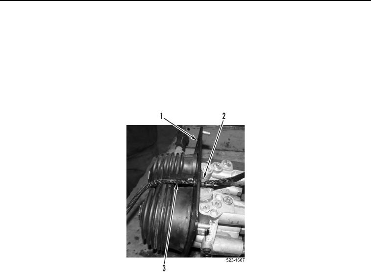
3. Install directional and downshift switches harness (Figure 8, Item 3) on pilot valve assembly (Figure 8, Item 1)
and install new tiedown strap (Figure 8, Item 2).
4. Install weatherproof connector on directional and downshift switches wiring harness (WP 0174).
Figure 8. Directional and Downshift Switches Wiring Harness.
0379