
TM 5-3805-298-23-4
0379
REMOVAL CONTINUED
NOTE
Cap and plug all hoses and fittings to prevent contamination.
Tag and mark hoses to aid installation.
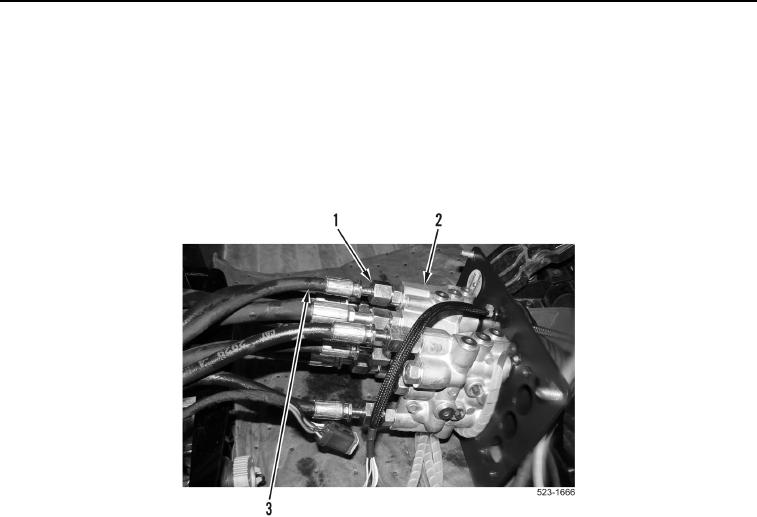
11. Loosen eight tube nuts (Figure 5, Item 1) and disconnect eight hoses (Figure 5, Item 3) from pilot valve
assembly (Figure 5, Item 2).
Figure 5. Pilot Valve Connections.
0379
12. Remove weatherproof connector from directional and downshift switches wiring harness (WP 0174).