
TM 5-3805-298-23-4
0379
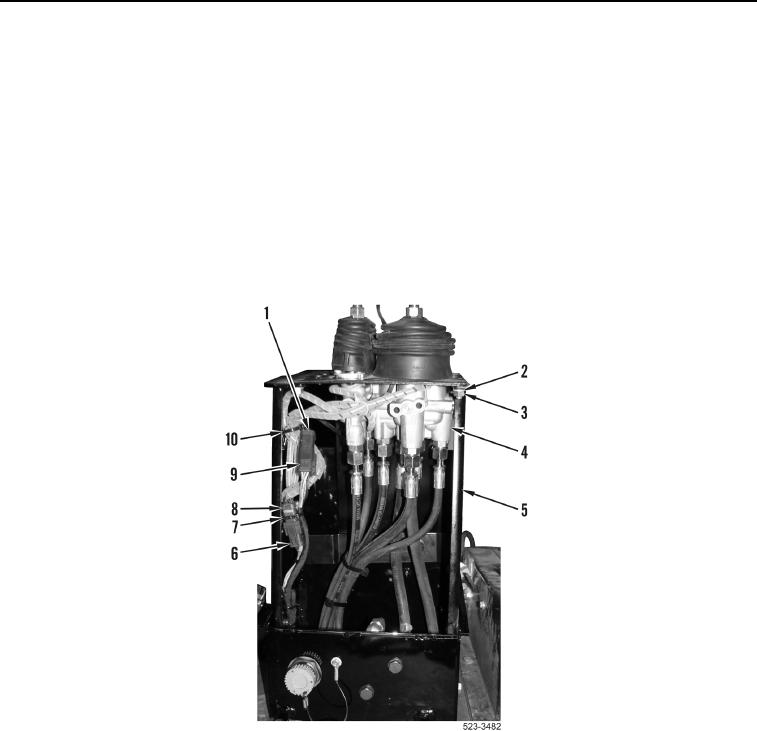
REMOVAL CONTINUED
NOTE
Note location and number of tiedown straps to aid installation.
Tag wiring harness connectors to aid installation.
7. Remove tiedown strap (Figure 4, Item 7) and disconnect pilot valve connector (Figure 4, Item 8) from lower cab
wiring harness connector (Figure 4, Item 6).
8. Remove tiedown strap (Figure 4, Item 10) and disconnect direction and downshift switches wiring harness
connector (Figure 4, Item 1) from lower cab wiring harness connector (Figure 4, Item 9).
9. Remove four nuts (Figure 4, Item 3) and washers (Figure 4, Item 2) from operator console (Figure 4, Item 5).
10. Position pilot valve assembly (Figure 4, Item 4) on cab floor.
Figure 4. Control Handle Connections.
0379