
TM 5-3805-298-23-4
0379
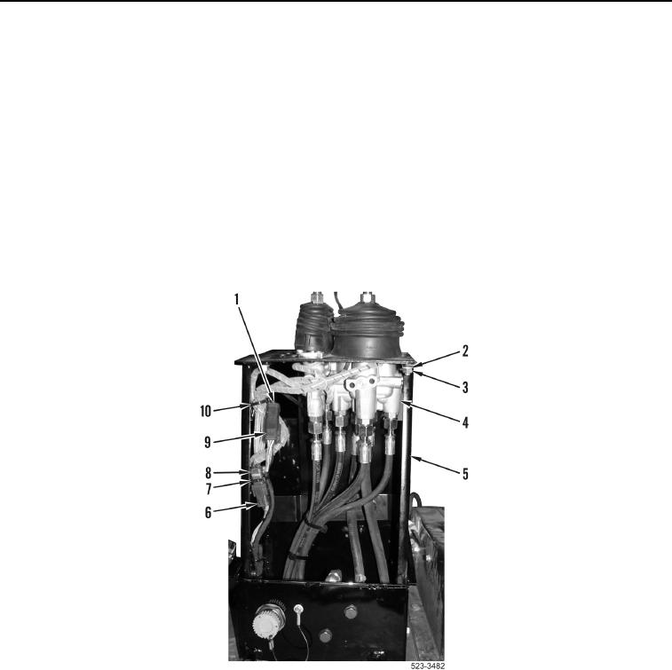
INSTALLATION CONTINUED
6. Install pilot valve assembly (Figure 10, Item 4), four washers (Figure 10, Item 2) and nuts (Figure 10, Item 3) on
operator console (Figure 10, Item 5).
7. Connect direction and downshift switches wiring harness connector (Figure 10, Item 1) to lower cab wiring
harness connector (Figure 10, Item 9).
NOTE
Install tiedown straps as noted during removal.
Install wiring harness connectors as noted during removal.
8. Install new tiedown strap (Figure 10, Item 10).
9. Connect pilot valve connector (Figure 10, Item 8) to lower cab wiring harness connector (Figure 10, Item 6).
10. Install new tiedown strap (Figure 10, Item 7).
Figure 10. Install Control Handle Connections.
0379