
TM 5-3805-298-23-4
0392
ASSEMBLY CONTINUED
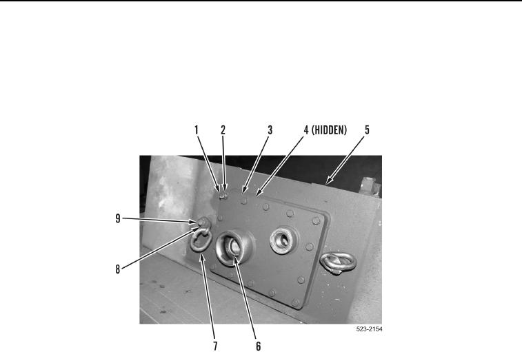
9. Install new gasket (Figure 15, Item 4), access plate (Figure 15, Item 3), 14 washers (Figure 15, Item 2) and
bolts (Figure 15, Item 1) on hydraulic tank (Figure 15, Item 5).
10. Install two bracket links (Figure 15, Item 7), washers (Figure 15, Item 8) and bolts (Figure 15, Item 9) on
hydraulic tank (Figure 15, Item 5).
11. Install fill screen (Figure 15, Item 6) on hydraulic tank (Figure 15, Item 5).
Figure 15. Access Plate.
0392