
TM 5-2420-231-23-3
0263
REMOVAL CONTINUED
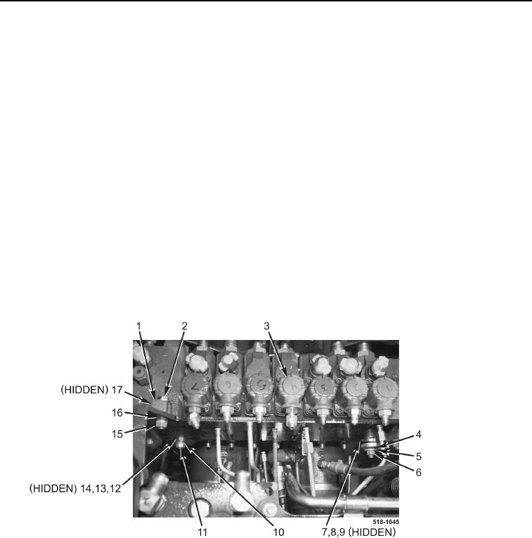
26. Remove nut (Figure 6, Item 6), lockwasher (Figure 6, Item 5), washer (Figure 6, Item 4), bolt (Figure 6, Item 7),
washer (Figure 6, Item 8), and spacer (Figure 6, Item 9) from backhoe control valve assembly (Figure 6,
Item 3). Discard lockwasher.
NOTE
Install nut no more than three full turns on bolt.
27. Install bolt (Figure 6, Item 7) and nut (Figure 6, Item 6) on backhoe control valve assembly (Figure 6, Item 3).
28. Remove nut (Figure 6, Item 15), lockwasher (Figure 6, Item 16), bolt (Figure 6, Item 2), washer (Figure 6,
Item 1), and spacer (Figure 6, Item 17) from backhoe control valve assembly (Figure 6, Item 3). Discard
lockwasher.
NOTE
Install nut no more than three full turns on bolt.
29. Install bolt (Figure 6, Item 2) and nut (Figure 6, Item 15) on backhoe control valve assembly (Figure 6, Item 3).
30. Remove nut (Figure 6, Item 11), lockwasher (Figure 6, Item 10), bolt (Figure 6, Item 12), washer (Figure 6,
Item 13), and spacer (Figure 6, Item 14) from backhoe control valve assembly (Figure 6, Item 3). Discard lock-
washer.
Figure 6. Bolts.
0263