
TM 5-2420-231-23-3
0263
REMOVAL CONTINUED
NOTE
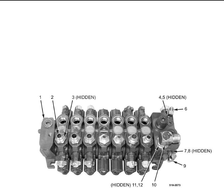
Note position and orientation of fittings to aid in installation.
36. Remove seven fittings (Figure 8, Item 2) and O-rings (Figure 8, Item 3) from backhoe control valve
(Figure 8, Item 1). Discard O-rings.
37. Loosen nut (Figure 8, Item 4) and remove fitting (Figure 8, Item 6) and O-ring (Figure 8, Item 5) from
backhoe control valve (Figure 8, Item 1). Discard O-ring.
38. Loosen nut (Figure 8, Item 11) and remove fitting (Figure 8, Item 10) and O-ring (Figure 8, Item 12) from back-
hoe control valve (Figure 8, Item 1). Discard O-ring.
39. Loosen nut (Figure 8 Item 7) and remove tee-fitting (Figure 8, Item 9) and O-ring (Figure 8, Item 8) from back-
hoe control valve (Figure 8, Item 1). Discard O-ring.
Figure 8. Backhoe Control Valve Fittings.
0263