
TM 5-2420-231-23-3
0279
REMOVAL CONTINUED
NOTE
Note location of clamps to aid in installation.
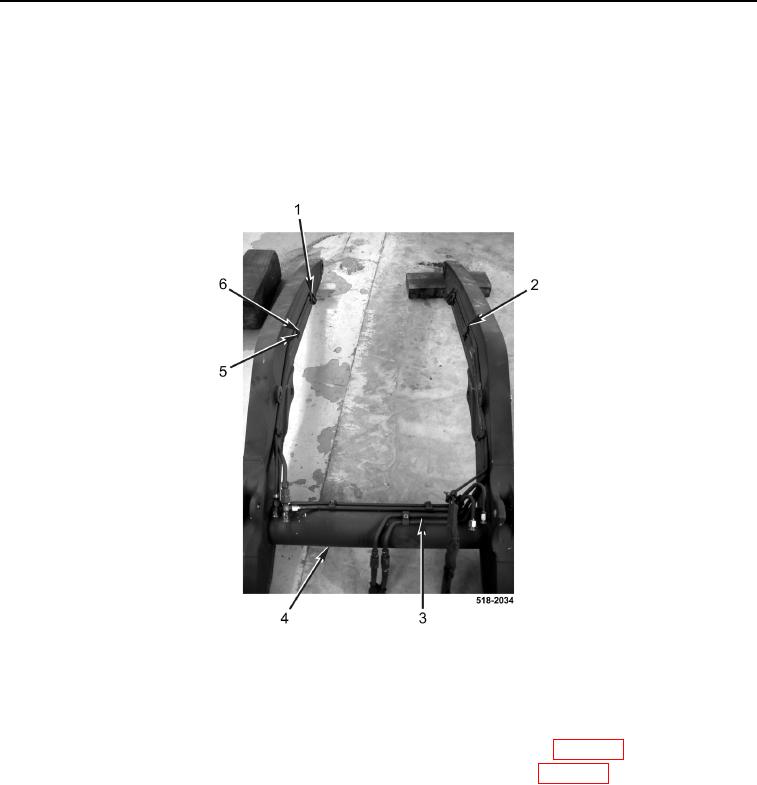
11. Remove nine nuts (Figure 6, Item 6), lockwashers (Figure 6, Item 5), six clamps (Figure 6, Item 1), three
clamps (Figure 6, Item 2), and tube assembly (Figure 6, Item 3) from lift frame (Figure 6, Item 4). Discard lock-
washers.
Figure 6. Tube Assembly.
0279
END OF TASK
CLEANING AND INSPECTION
0279
1. Clean and inspect all parts IAW Mechanical General Maintenance Instructions (WP 0369).
2. Clean and inspect all parts IAW Electrical General Maintenance Instructions (WP 0370).
END OF TASK