• Home
  • Download PDF
  • Order CD-ROM
  • Order in Print
Figure 2. Hoses and Tubes (Right Side).
Figure 5. Lift Frame Removal.

Tractor, Wheeled, Industrial Backhoe Loader Nsn 2420-01-532-3399
Page Navigation
  436    437    438    439    440  441  442    443    444    445    446  
img
.
TM 5-2420-231-23-3
0279
REMOVAL CONTINUED
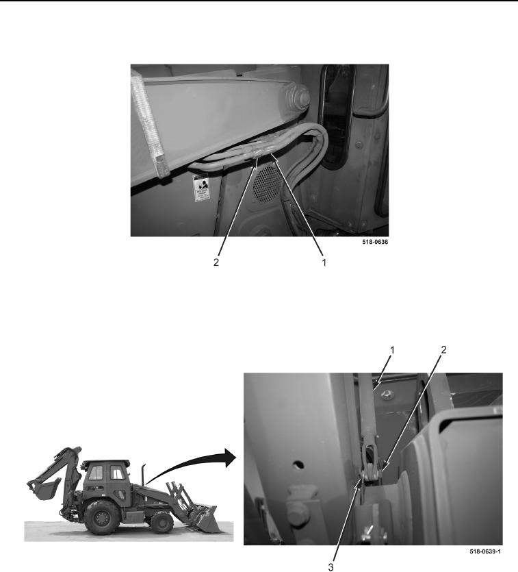
5. Disconnect four hoses (Figure 3, Item 2) from tubes (Figure 3, Item 1) on left side of loader.
Figure 3. Hoses and Tubes (Left Side).
0279
6. Remove cotter pin (Figure 4, Item 3), clevis pin (Figure 4, Item 2), and rod (Figure 4, Item 1) from machine.
Discard cotter pin.
Figure 4. Rod.
0279
0279-3


Privacy Statement
Press Release
Contact

© Copyright Integrated Publishing, Inc.. All Rights Reserved.