• Home
  • Download PDF
  • Order CD-ROM
  • Order in Print
Figure 6. Tube Assembly.
Figure 8. Lift Frame Installation.

Tractor, Wheeled, Industrial Backhoe Loader Nsn 2420-01-532-3399
Page Navigation
  439    440    441    442    443  444  445    446    447    448    449  
img
.
TM 5-2420-231-23-3
0279
INSTALLATION
0279
NOTE
Install clamps in position and orientation noted during removal.
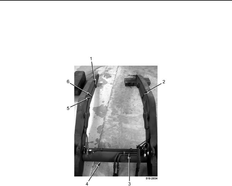
1. Install tube assembly (Figure 7, Item 3), three clamps (Figure 7, Item 2), six clamps (Figure 7, Item 1), nine
new lockwashers (Figure 7, Item 5), and nuts (Figure 7, Item 6) on lift frame (Figure 7, Item 4).
Figure 7. Tube Assembly.
0279
0279-6


Privacy Statement
Press Release
Contact

© Copyright Integrated Publishing, Inc.. All Rights Reserved.