TM 5-3805-258-24-1
FUEL SYSTEM
T E S T I N G A N D A D J U S T I NG
the fuel pump housing, the bracket lever must
move smoothly when the governor is moved
from low idle to high idle.
T I M I N G P I N I N S T A L L ED
8. 7N1048 Timing Pin.
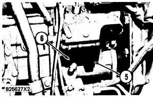
B R A C K E T
A S S E M B L Y
I N S T A L L ED
5. Bracket assembly. 6. 5P4814 Collet.
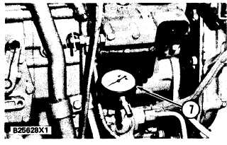
4. Put 9S229 Contact Point on 6V3075 Dial
Indicator (7) and install dial indicator in collet
(6). Tighten the collet only enough to hold
dial indicator.
D I A L I N D I C A T O R I N S T A L L ED
7. 6V3075 Dial Indicator.
5. Move the governor control lever to the FUEL
OFF position (rotate governor shaft clock-
wise). Install 7N1048 Timing Pin (8) in the
hole in the bracket assembly. Push the timing
pin in until contact is made with the fuel rack.
6. Move the governor control lever to the HIGH
IDLE position (rotate governor shaft counter-
clockwise) and hold in this position. The fuel
rack will move against the timing pin and stop.
This is the rack zero position. Loosen collet
(6) and adjust the revolution counter on the
dial indicator to zero. Tighten collet (6) just
enough to hold the indicator in this position.
Move the dial of the indicator to get align-
ment of the pointer and zero. Remove the
timing pin.
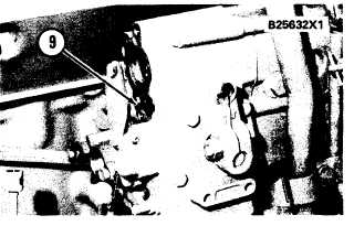
7. Move the governor control lever to the FUEL
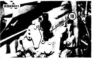
OFF position. Remove the air fuel ratio con-
trol. If filter screen (9) extends beyond the sur-
face of the governor housing, remove the filter
screen. Use two S1614 Bolts and install 6V2017
Governor Adjustment Tool (10). Be sure the
end of the tool is behind the governor linkage
and that the flange is completely against the
governor housing.
A I R F U E L R A T I O C O N T R O L R E M O V ED
( T Y P I C A L E X A M P L E)
9. Filter screen.
A D J U S T I N G T O O L I N S T A L L E D
( T Y P I C A L E X A M P L E )
4-20
10. 6V2017 Governor Adjustment Tool.