F U E L S Y S T E M
TM 5-3805-258-24-1
F U E L S Y S T E M
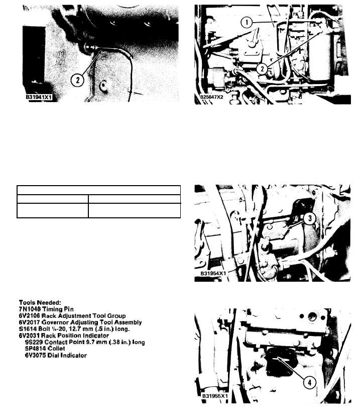
T R A N S D U C E R I N P O S I T I O N
2 . T D C m a g n e t i c t r a n s d u c e r .
The TIMING CHART gives the acceptable dyn-
amic (engine in motion) timing range as read on the
Timing Indicator Group. The TIMING CHART is
for the 3304 Engine with 20 ± 1° static (engine
stopped) timing.
TIMING CHART
ENGINE rpm
INDICATOR READING
7
0
0
1 9 . 5 t o 2 1 . 9 °
2
3
0
0
2 1 . 1 t o 2 3 . 5 °
If the engine timing is not correct, make reference
to CHECKING TIMING BY TIMING PIN
METHOD for the procedure to change engine
timing.
GOVERNOR ADJUSTMENT FOR AIR FUEL
RATIO CONTROL
Tools Needed:
7N1048 Timing Pin
6V2106 Rack Adjustment Tool Group
6V2017 Governor Adjusting Tool Assembly
S1614 Bolt ‘/,-20, 12.7 mm (.5 in.) long.
6V2031 Rack Position Indicator
9S229 Contact Point 9.7 mm (.38 in.) long
5P4814 Collet
6V3075 Dial Indicator
The governor adjustment for the air fuel ratio
control can be done with the fuel injection pump
and governor on or off the engine.
NOTE: The air fuel ratio control is set to specific
dimensions at the factory. If the control is dis-
assembled it must be set again on the 6V2029 Fix-
ture Group before the governor adjustment is made.
R I G H T S I D E O F E N G I NE
( T Y P I C A L E X A M P L E )
1. Fuel line. 2. Fuel filter base.
1. Remove fuel line (1) and fuel filter base (2)
and fuel filter from the fuel injection housing.
2. Remove cover (3) from the side of the fuel
injection pump housing.
F U E L I N J E C T I O N P U M P A N D G O V E R N O R
3. Cover.
C O V E R
R E M O V E D
4. Slot on fuel rack.
3. Install 5P4814 Collet (6) on bracket assembly
(5). Install the bracket assembly on the fuel
pump housing. The lever on the bracket as-
sembly must be in slot (4) on the fuel rack.
4-19
After the bracket assembly is tightened to